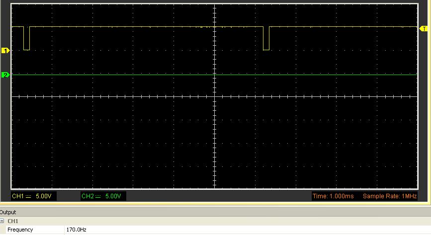
Info regarding pin 22 and (23 & 24)
Measured at different Hz to show the findings
0 till 60Hz
Pin 22 ignition outcome (Yellow) the same as ignition income pin 22 an 23 (Green) I call this back off the lobe ignition pulse
(22 an 23 are connected to each other)
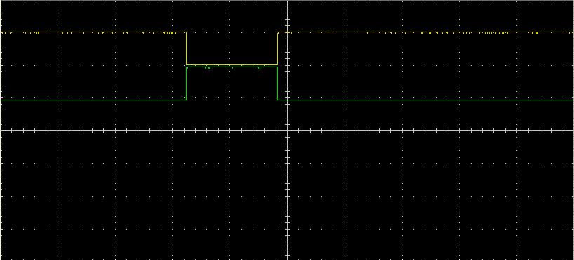
70 till 170Hz
You see that pin 22 (Yellow) has a calculated ignition pulse (before the ignition pulse back off the lobe)
(Green) is pin 23 an 24 still the "back off the lob" incoming signal
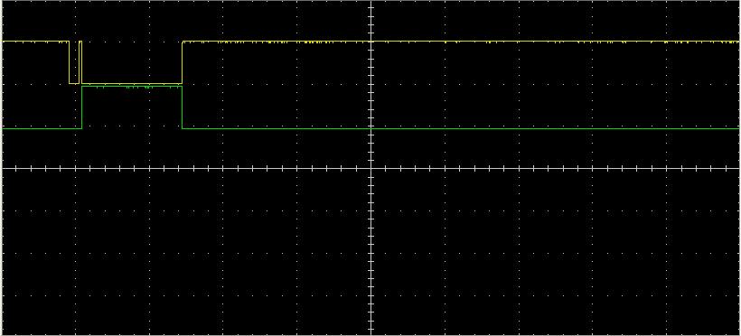
100Hz
Her I show the 100Hz but with TPS set on 1 (low ignition curve)
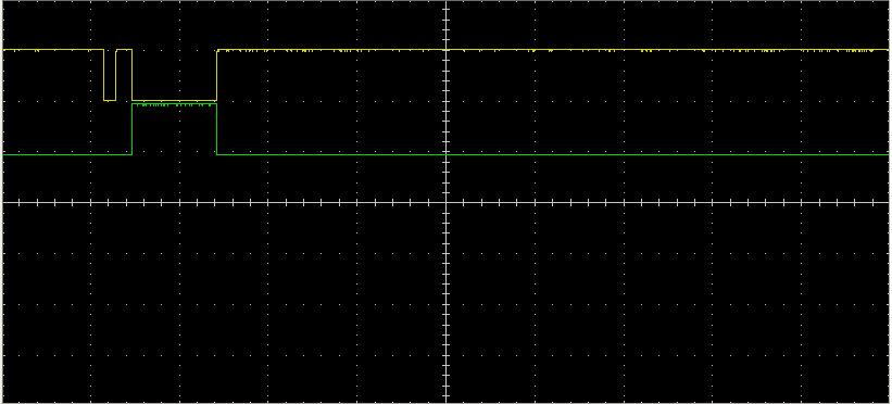
100Hz
Her I show the 100Hz but with TPS set on 0 (High ignition curve)
you can see the shifting off degrees as the small yellow block is moved to the left
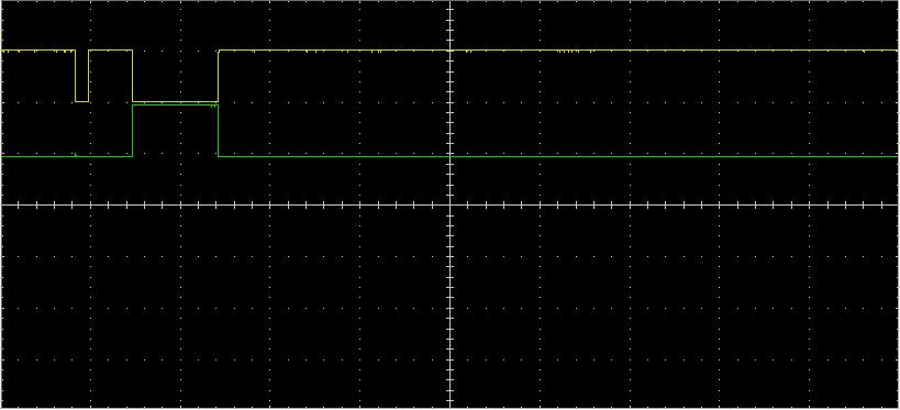
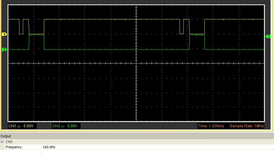
160Hz
Her is the point where the incoming back off the lobe signal is stopping. After this only the calculated ignition is present
170Hz till end
As you can see, only the calculated pulse is there.
From this point till the end its only this ignition pulse in use
