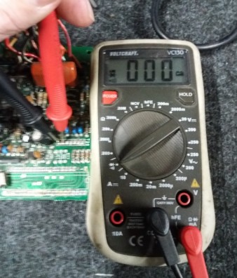
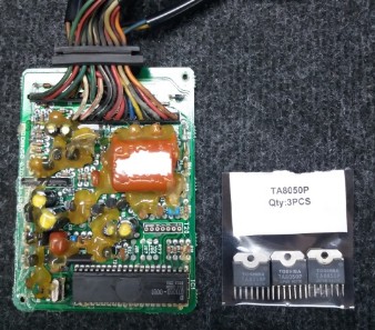
The TA8050P is a servo driver with controls the ypvs motor. The in and out controlling signals are received on pin 1 and 2 from the main IC
On Pin 3 and 5 are the servo + and - signals (control fore the ypvs motor) pin 4 is the ground pin 7 is the 5V supply
Pin 6 should not be connected as it is internally a loose contact.
The big question remains way did YAMAHA connect PIN 6 and 7 witch each other.
This needs a further investigation.

To investigate this, I have to remove the TA8050P
Located in the red circle
Soldering it loose, turns out to be a big challenge
Did managed to remove it
Sadly not completely intact, so have ordered three new TA8050P's. (For testing)
To make sure I didn't need to solder it again, mounted a holder.
Now it will be easier to mound the TA8050P ones it arrives, I just push pin6 away and all should be fine.
21-12-2019
Today the Three TA8050P's arrived so I could test the difference between Pin 6 connected and not connected.
The setup is easy as the Chip mounds perfect in the socket

Test results measured with all pins connected. (original setup)
Test results measured with pin 6 not connected. (changed setup)
Test results measured with pin 6 connected at ground. (changed setup)
Sadly there is no difference between the three setup's
Pin 6 seems not to be effected by the voltage given from Pin 7
See the results
| Chip TA8050P | All pins connected | Pin 6 not connected | Pin 6 on ground |
| 0Hz | Fully Open | Fully Open | Fully Open |
| 30Hz | Fully Closed | Fully Closed | Fully Closed |
| 320Hz | Fully Open | Fully Open | Fully Open |
| 360/370Hz | Speed Limiter | Speed Limiter | Speed Limiter |


